Geometry and Materials
The Tower is made exclusively of wrought iron, although steel was available at the time. Eiffel chose iron because steel was more expensive since it was a new development, and also because he was experienced and confident in iron design.
Structural towers can be divided into two groups: columns, which are designed to primarily resist dead loads, and cantilevers, which are designed to primarily resist wind loads. This distinction can be made mathematically by the following relation:
This measure is a ratio of the axial forces created by the dead load (NG) and the wind load (NW), and is used to determine how well a structure’s design accounts for wind loads. The general rule of thumb which is accepted by building codes is that a structure may be overstressed by wind by 33% (hence the 4/3 factor) before special design is necessary, i.e., the axial force created by the wind can be up to one-third of the axial force from the dead load. If this requirement is met, the structure can be designed simply as a column because it is assumed that the wind forces will be ‘absorbed’ by the safety factors.
The following analysis for the
As a visual comparison, one may
think of the ,
but weighs four times as much! (90,100 k
vs. 22,280 k) For the
The Tower is used to introduce
the cantilever as a structural form because it illustrates the most efficient
cantilever form one that is splayed at the support. Although the
The Tower is a rather complex structure in detail, especially in its geometry, and to some extent, in its loading. Therefore, the analysis will make some simplifications and idealizations concerning both its geometry and loading. After a discussion of the geometry and loading, the support reactions, the internal forces and the internal stresses are all computed. To complete the analysis both the safety and the efficiency of the design are evaluated.
Eiffel designed the Tower to be 300 meters high, which is 984 feet (approximately 90 stories); it is 328 feet wide at its base. This dimension quickly tapers as illustrated by the following diagram and chart. There are four observation decks located as shown in the diagram. For analysis, the Tower will be divided into three parts as indicated on the same diagram. The widths of the Tower corresponding to each of these heights have been calculated from the equations for a parabola, which is an idealization of the Tower’s shape; its true shape is somewhat more sharply curved than a parabola.
|
Location |
Height (ft) |
Width (ft) |
|
|
Support |
0 |
328 |
18.4 |
|
First Platform |
186 |
216 |
15.1 |
|
Second Platform |
380 |
123 |
11.6 |
|
Intermediate Platform |
644 |
40 |
6.6 |
|
Top Platform |
906 |
2 |
1.5 |
|
Top |
984 |
0 |
0.0 |
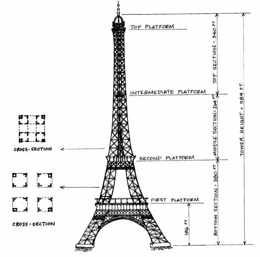
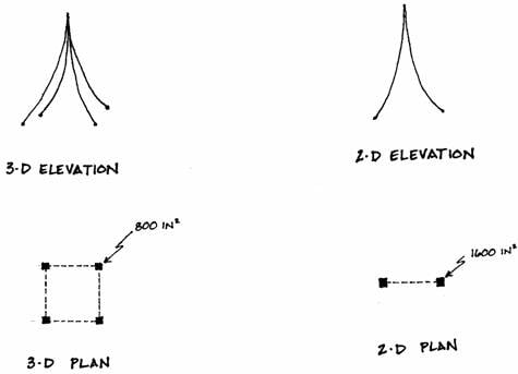
The basic structure of the Tower is lattice-work columns at each of the four corners of the Tower, in which diagonals connect four elements, thus making stiff, but lightweight columns. Typical sections illustrating these columns can be seen next to their positions along the Tower in the large diagram above. Such composite structural elements require detailed calculations in analysis, so the composite columns are idealized by single solid cross section columns, each with an area of 800 square inches.
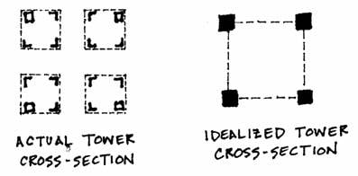
These four elements are assumed to rise along the curve of the actual columns of the Tower and meet near the top.
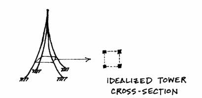
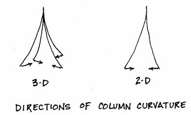
This idealization, however, is still three-dimensional and must be further simplified to two dimensions for this simple analysis. This is accomplished by essentially combining the two front and the two back columns into two of double thickness. This results in an area of 1600 square inches for each of the simplified supports.
One should realize that in this simplification the curve of the columns is altered. In the three-dimensional structure the curve is toward the center of the square base, but in the two-dimensional simplification the curve is in the plane of the model, and therefore, decreased somewhat.
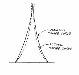
This change is slight, however, in light of the idealizations of the Tower’s form. The analysis will assume that the curved elements follow a parabola, but actually they curve more sharply than this, as illustrated in the following diagram. This more curved shape was selected because it was the most efficient in resisting the wind load (which is really not uniform, as it is presently assumed to be.)
One further point must be made about the geometry of the model: the overall structure has a vertical axis between the two columns, but, individually, each column has its own axis that follows the curve of the elements. These axes are idealized as parabolas.
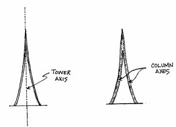
Overall internal forces are found from an analysis centered on the tower axis. Internal forces in the individual elements, which act on the curved element axes, are found from the overall forces. When the tower axis is used, the connections between the columns will be idealized as continuous. They are actually continuous above the second platform, but below this point, they are made only by the lower platform and the ground.
Introduction Geometry Loads Reactions Internal Forces Stresses Efficiency Explore