Facilities


Wave Tank
Dimensions: 18.3 m x 2.5 m x 1 m deep
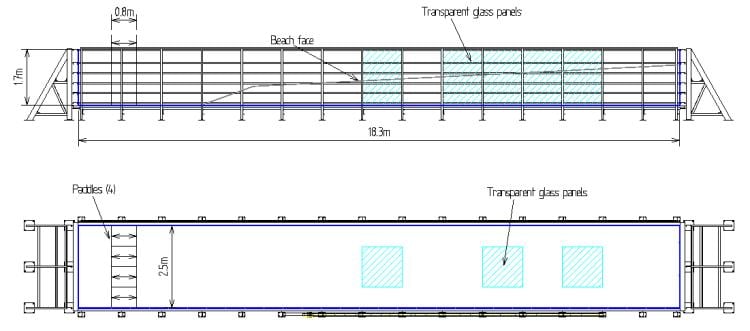
TOP: Side-view of wave tank schematic. BOTTOM: Plan-view of wave tank schematic.

The Coastal Engineering Laboratory wave tank is comprised of a steel frame with channels running along both the sides and bottom of the tank. The side walls and bottom are primarily 1 in (2.54 cm) marine-grade plywood panels. Eleven sheets of 3/4 in (1.9 cm) glass make up the remainder of the side and bottom panels. A 30 ft (9.14 m) linear-rail set runs along the top of one side of the tank over the glass side walls. A steel T-rail runs the full length of the other side. Two instrument carts will run on these rails. The beach is to be constructed of plastic panels supported by an aluminum frame with the main section running 13 m at a slope of 1:20.


Wavemaker Construction
Currently under construction is a directional wavemaker. The uniquely designed system is to have four independently controlled hydraulic piston actuated paddels. Each paddle will have a 30 in (0.76 m) stroke. Each actuator is controlled by a Parker high response proportional servo valve. Fluid is delivered to the valves by two 20 gpm hydraulic power units operating in series.

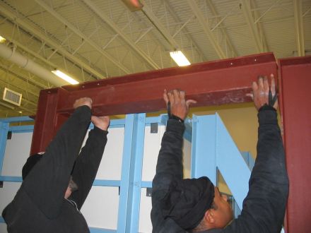
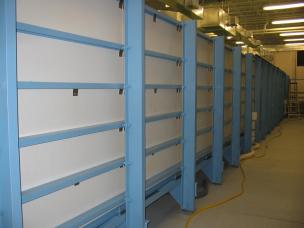
All columns in place on west side of tank. Placing a short beam with brute strength.
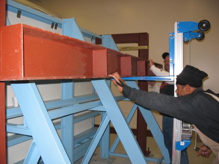
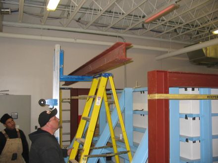
Lifting one of the small cross-channel beams over the tank. Balancing one of the large cross-channel beams on the lift.

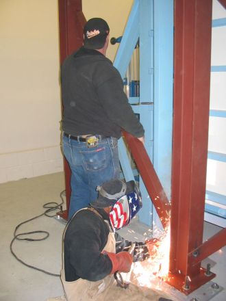
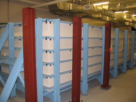
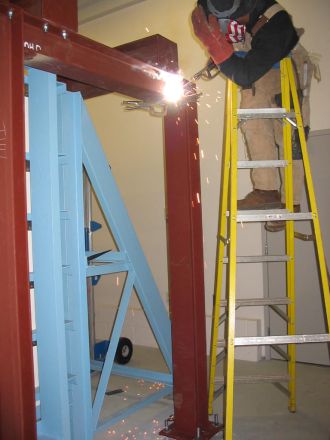
All beams and columns are in place. Tack welding a small beam. Tacking the cross-bracing.

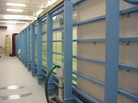
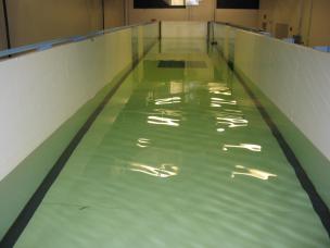
Don't look at the arc, you'll hurt your eyes. Looking down from the far end of the tank.


More Laboratory/Wavemaker Construction

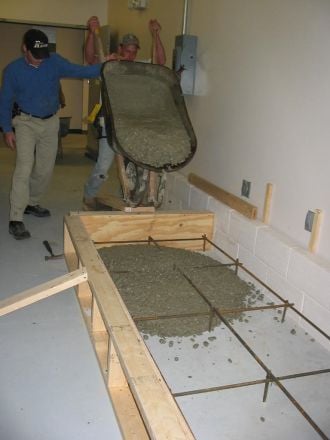
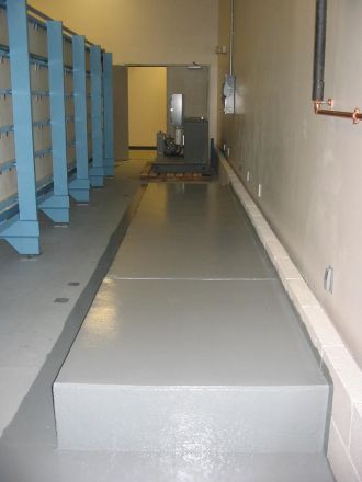
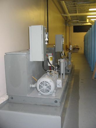
10/9/03: Pouring an elevated concrete pad for the hydraulic power units. 12/1/03, 8:30 AM: Finished pad, all ready for placement of power units. 12/1/03, 12:00 PM: Power units in place!


Back to the Coastal Engineering Lab


Questions or Comments? Please email [email protected].
Modified: 12/17/03