Internal Forces
Forces from Vertical Loads Forces from Horizontal Loads Total Axial Forces
The internal forces in the columns are found using the reactions, the loads and the principles of equilibrium. The simplest internal forces are the axial ones, which result from the vertical loads and reactions. They reach a maximum at the base of the Tower.
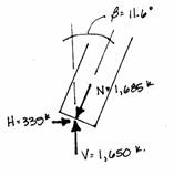
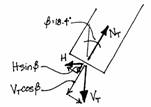
The axial force in the columns is the inclined force, N, shown acting along the axis of one column. This force is equal to the combination of a vertical and a horizontal component. The gravity loads and reactions are vertical and create the vertical component; the horizontal component develops because the vertical forces are carried in an inclined column, i.e., for the columns to be in equilibrium there must be a horizontal component of the axial force.
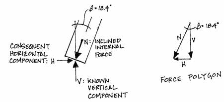
These three forces create a
‘force polygon’ where, drawn head to tail, the scaled components are equal to
the axial force and three form a closed shape.
The magnitudes of the horizontal components and the axial force can be
found from the vertical force and the angle of the column axis with
trigonometry. The chart shown in the
geometry section gives the slope of the columns at the base as . The simple trigonometric relationship
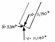
can be rearranged to find N:
This is the axial force that is developed in both columns at their bases. The horizontal components at the base can be found from the trigonometric formula:
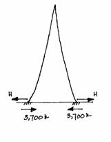
These horizontal forces tend to push the Tower apart but are resisted by the connection all along the Tower and the ground. This can be visualized if one imagines a ladder propped against a building. If there was no friction between the ground and ladder base, or if the base was on wheels, the ladder would slide away from the wall.
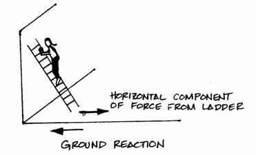
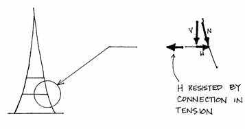
In the same manner, the columns of the Tower would slide apart if there were no connections between them. These connections, which have been idealized as continuous, experience tension force equal to the horizontal forces they are resisting.
At the base, the ground will resist with horizontal reactions of 3700 kips acting inward.
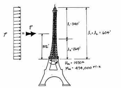
The axial force will decrease with height as the vertical load and angle of inclination decrease. As an example, the axial force at the second platform will be found. The entire top and middle parts are above this point, therefore, the vertical load is:
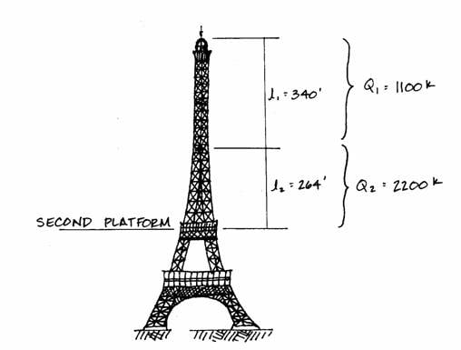
The chart given in the Geometry
section shows that at this height of 380 feet, the slope of the elements is . The trigonometric formula:
is used to find:
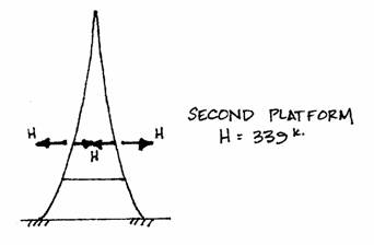
The value at the base is almost seven times this value! The compression forces from the dead load will be identical in both of the columns because they are each taking half of the vertical load. (The cross-sectional area could be decreased at the higher point because the smaller compression force would create a small compressive stress. This is indeed what Eiffel did, as shown in the earlier figure; this is neglected in the simplification.) The horizontal component of the axial force at the second platform is:
This force will be resisted by the connection made by the second platform itself.
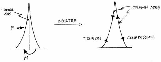
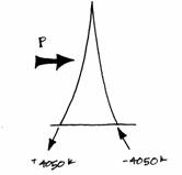
The internal forces created by the overall bending moment are investigated next. The bending moment from the wind load can be found at any point if the entire structure is treated as a single unit rather than as two columns. The bending moment is found around the tower axis, whereas the axial forces were found along the columns’ axes. The overall bending moment from the horizontal wind load will produce tension (T) in one column and compression (C) in the other. Exaggerated action under wind load is shown:

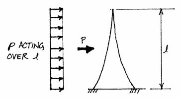
The values of the bending moment all along the height of the Tower must be known to find the resulting tension and compression forces in the columns. A bending moment diagram illustrates the continuous values. The horizontal force creating the bending moment is the wind, simplified as a point load acting at the mid-point of the area under consideration.
At a point a distance ‘x’ from
the bottom as shown in the diagram below, the bending moment is found using as the magnitude of the point load and
as the distance.
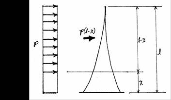
The equation for the moment at any point along the Tower uses these two values:
For the
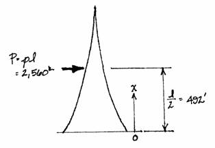
The reaction formula used
earlier, ,
is a simplified version of this formula where x = 0 and where
.
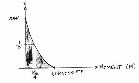
The graph of the equation with changing values of x is a diagram of the continuous bending moment along the Tower. The shape is also a parabola, only the
magnitude is different.
The shape of the
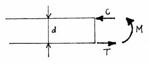
At any point along the height of the Tower, the overall bending moment, M, and the width of the structure, d, are used to determine the value of both the tension (T) and compression (C) forces (which are equal) from the formula:
This formula was justified in the Monument analysis where it was shown that the tension or compression forces result from the bending moment acting over the depth (or width here) of the structure.
This calculation uses the bending moments found around the tower axis to find axial forces that act along the column axes.
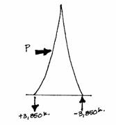
At the base of the Tower the moment force is M = 1,260,000 ft-k (the reaction force), and the width, d, is 328 feet. Therefore,
where T = +3,850 k and C = -3,850 k because compression forces are designated as negative. Both of these forces are vertical reactions to the wind.
The axial forces in the inclined elements resulting from the wind load are found from the vertical reactions and the horizontal reactions to the wind found earlier.
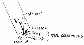
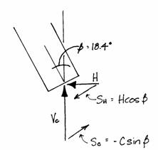
On the leeward side, where the
wind creates a vertical compression reaction, Vc and H
contribute part of their forces along the axis of the column. The compression force, Vc, contributes a component of to the axial force, Nc and H
contributes
to Nc. Nc
can be found from Vc, H and the angle at the base of the column,
. Negative signs are used because the axial
force is compressive.
The windward side will have a positive value of N because Vt and H create axial tension:
The axial forces produced by the
horizontal load of the wind are .
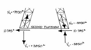
To further illustrate this idea, the axial forces produced by the wind load at the second platform will be investigated. The horizontal and bending moment reactions from the wind on the top and middle parts of the Tower are found with a free-body diagram cut at the second platform.
where
The chart shows that d = 123 ft at the second platform, so the tension and compression are:
Hm is found as in each column. With these values Nc and Nt
can be found using the formulas introduced earlier:
The axial forces and the vertical
components are nearly equal. This
illustrates that at a small angle these calculations hardly need be performed,
especially considering the simplicity of this analysis. Generally at an angle less than ,
one can consider the axial force and vertical force equal. The vertical forces, Vt and Vc,
at this height are roughly equal to the vertical tension and compression found
at the base; they are all roughly 4,000 kips.
This shows that if the shape of a structure imitates the shape of its
bending moment diagram, the vertical forces created by the bending moment will
be constant all along its height. The
width of the base is equally capable of resisting the bending moment at the
base as the width at the second platform is capable of resisting the bending
moment at that point.
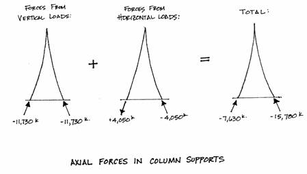
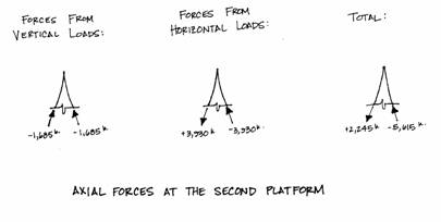
Now that the axial forces from both vertical and horizontal loads have been calculated, the total axial forces in the column supports are found by simply adding the axial force found from the two loads. Compression forces are negative and tension forces are positive. This is shown in the first diagram, below. The second diagram shows the corresponding forces at the second platform.
At this point (the second
platform) the windward column experiences tension forces rather than the
compression found near the base. This
creates no structural problems because wrought iron resists tension just as well
as compression. Next, the total axial
forces are used to find the internal stress. First, however, a quick investigation of the
shear force in the columns further illustrates the efficient shape of the
Tower. Since the shape of the Tower
nearly imitates the shape of the moment diagram, and since the vertical
compression force has been found to be constant all along the Tower’s height,
there should, theoretically, be no shear force in the column from the
horizontal wind load. This is
investigated using the vertical compression and horizontal forces found
earlier. (See the diagram at the top of
the next page.) Where and
,
the total shear force is found by the formula:
This result verifies the concept that, from the wind load, the parabolic shape of the Tower will allow only uniform vertical forces, and axial forces that decrease with the angle of the columns.
Introduction Geometry Loads Reactions Internal Forces Stresses Efficiency Explore